Global buyers entering 2026 need more than a catalog of cutting tools. They need a dependable Milling Machining strategy, matched to material, tolerance, batch size, and delivery pressure. A titanium aerospace bracket, for example, demands different cutter geometry and cooling control than an aluminum housing. Small choices can create large cost differences.
Professor Yusuf Altintas, a leading authority in machining science, has expressed a practical principle: “Machining must connect cutting theory with measurable production results.” That idea guides this review. It shifts attention from impressive machine specifications toward spindle stability, tool life, surface finish, inspection data, and repeatable output. Numbers matter.
This article examines the best milling methods for international buyers in 2026. It compares three-axis, four-axis, five-axis, high-speed, and precision Milling Machining approaches. It also considers automation, workholding, material behavior, energy use, and supplier communication. These details often decide whether a project succeeds after the purchase order is signed.
There is no universal winner. A five-axis machine may reduce setups, yet it can increase programming demands and maintenance costs. A simpler three-axis system may perform better for stable, high-volume work. Buyers should question unclear tolerances, unsupported cycle-time promises, and vague inspection procedures. Even experienced teams miss details sometimes. That weakness deserves attention.
Reliable sourcing requires evidence: sample parts, capability studies, calibrated measuring equipment, and transparent production records. The following guide offers a practical framework for selecting Milling Machining methods with greater confidence, fewer surprises, and realistic long-term value.
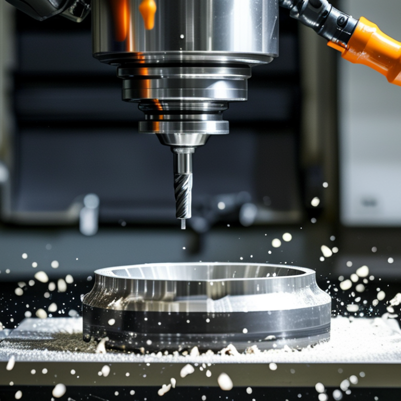
Milling Machining Fundamentals and Key Process Categories
Milling machining removes material with a rotating cutter and a controlled workpiece movement. The cutter’s teeth create chips, not smooth shavings. Cutting speed, feed rate, depth of cut, and tool diameter directly affect accuracy and surface quality. Workholding must resist vibration, especially during deep pocketing or thin-wall machining. A loose fixture can ruin an otherwise accurate program.
Common process categories include face milling, plain milling, slot milling, pocket milling, contour milling, and drilling. Face milling creates flat reference surfaces. Slot milling produces channels for keys, seals, or assembly parts. Pocket milling removes internal material around raised features. Contour milling follows curved edges and complex profiles. Five-axis movement can reach angled surfaces, but it also demands stronger programming control and inspection planning.
Material changes the entire approach. Aluminum often accepts higher cutting speeds, while stainless steel may generate heat and work hardening. Hardened steel needs suitable tooling, stable clamping, and carefully controlled passes. I have seen buyers focus on tolerance numbers while ignoring datum design. That creates avoidable disputes. Clear drawings should define material grade, critical dimensions, surface finish, edge breaks, and inspection methods. Sample reports, measured first articles, and photographs of finished features improve communication across borders. Not every tight tolerance is necessary. Sometimes, the drawing needs another review before machining begins.
Choosing a milling method starts with the material, not the machine. Aluminum cuts quickly, but thin walls can vibrate and lose accuracy. Use sharp tools, high cutting speeds, and light finishing passes. For carbon steel, balanced roughing removes stock without overheating the edge. Stainless steel needs controlled heat and steady tool engagement. Otherwise, work hardening appears. Titanium demands slower cutting, strong fixturing, and careful chip evacuation.
Part geometry changes the decision. A three-axis process suits open faces, pockets, and simple prismatic parts. Add rotary positioning for features around several sides. Five-axis milling reaches angled surfaces with fewer setups. That can reduce alignment errors on turbine-like or medical components. Deep cavities require long tools, but long tools also deflect. A shorter tool and another setup may be more reliable. This trade-off is often missed in quotations. Thin ribs need lower cutting pressure and firm, distributed support.
For hardened steel, carbide tooling and rigid high-speed finishing can protect surface quality. For engineering plastics, lower heat generation matters more than maximum removal rate. Choose conventional or climb milling after checking machine rigidity and workholding. Climb milling often improves finish, yet it can pull a poorly secured part. Verify tolerances with a first article, not assumptions. Review tool wear, burrs, and measured dimensions before approving volume production. No chart replaces a test cut. I would question any quote that hides setup count or inspection method. Clear drawings, material certificates, and inspection records make cross-border sourcing safer.
For global buyers, CNC milling in 2026 is less about cutting speed alone. It is about predictable results across shifts, operators, and production sites. Modern five-axis machines can reach angled surfaces in fewer setups. That reduces fixture changes, handling marks, and alignment errors. Adaptive toolpaths adjust cutting conditions when spindle load changes. The improvement is practical: steadier chips, cooler tools, and fewer rejected housings.
Automation now connects pallet changers, robotic loading, tool presetting, and in-process probing. A probe checks datum locations before critical cuts. Tool-life monitoring can flag unusual vibration before a cutter fails. Digital work instructions also help operators repeat approved setups. Yet automation needs disciplined input. Poor offsets create automated scrap. A fast machine can repeat a mistake perfectly.
Reliable suppliers should show inspection records, material traceability, capability studies, and controlled revision histories. Buyers should ask how alarms are reviewed, not merely whether sensors exist. For tight features, request actual measurement data from comparable parts. Surface finish, burr control, and edge condition deserve equal attention. No system is flawless. Even strong process plans need human review when geometry changes. Cycle-time targets can also hide maintenance delays or unstable tooling. Process audits should examine alarm trends, tool wear, probing results, and dimensional drift.
Global buyers should judge milling methods through four practical filters: quality, cost, lead time, and compliance. CNC milling remains effective for tight tolerances, complex pockets, and repeat production. However, the best method depends on material, batch size, surface-finish needs, and inspection requirements. A cheaper three-axis process may create extra setups, longer inspection time, and hidden rework costs.
Ask for capability data, inspection records, calibration status, and full material traceability. The ISO Survey 2023 reported more than 1.26 million ISO 9001 certificates worldwide, yet certification alone cannot prove machining accuracy. Request sample reports with dimensional results. Better evidence matters.
The World Bank’s 2023 Logistics Performance Index shows clear differences in customs, infrastructure, and shipment reliability across markets. Buyers should confirm raw-material availability, machine capacity, first-article timing, packaging, and backup plans. One missed drawing revision can disrupt everything. It happens.
Compliance documents may include certificates of origin, restricted-substance declarations, and industry-specific records. Requirements vary by destination and application. I would not accept vague claims such as “fully compliant.” A controlled document trail is stronger. Even experienced teams sometimes underprice communication, which is an uncomfortable but useful lesson for 2026 sourcing decisions.
2026 Best Milling Machining Methods for Global Buyers?
Selecting the best milling method starts with the part, not the machine brochure. Define material hardness, feature depth, tolerance, batch size, and surface-finish requirements. A flat aluminum plate may need face milling and three-axis pocketing. A medical housing with angled cavities may justify five-axis machining. Keep it practical.
The 2024 Deloitte Global Manufacturing Industry Outlook reported that 86% of manufacturing leaders viewed smart-factory investment as important for competitiveness. Buyers should therefore request usable production data, not vague automation claims. Ask for cycle-time records, tool-life evidence, inspection reports, and sample tolerances. For difficult alloys, compare high-speed milling, adaptive toolpaths, and lower-speed roughing. The cheapest hourly rate can become expensive after rework.
Use a simple decision gate. Choose three-axis milling for accessible prismatic features and stable volumes. Consider four- or five-axis machining when repositioning creates alignment risk. Check spindle power, travel, coolant delivery, probing, and local service support. Grand View Research has projected strong growth in the global CNC machine market through 2030, reflecting wider adoption and more supplier choices. More choices can confuse buyers. I have seen specifications look perfect, yet the first trial exposed chatter near a thin wall. Allow a pilot run, measure the actual part, and revise the method before signing a large order.
| Step | Milling Method | Primary Cutting Action | Best Workpiece Features | Suitable Materials | Main Advantages | Key Limitations | Buyer Selection Check |
|---|---|---|---|---|---|---|---|
| 1 | Face Milling | The cutter axis is generally perpendicular to the machined surface; the face of the cutter produces a flat plane. | Large flat surfaces, datum faces, plate stock, and preparation before finishing. | Aluminum alloys, steels, stainless steels, cast irons, and many non-ferrous metals. | High material-removal capability; efficient for creating accurate reference surfaces. | Less suitable for deep narrow pockets; cutter engagement and workholding must be controlled. | Check required flatness, surface-finish target, spindle power, cutter diameter, and workholding rigidity. |
| 2 | Peripheral or Slab Milling | The cutter teeth on the cylindrical circumference remove material from the side or top of a workpiece. | Long horizontal surfaces, wide steps, and high-volume stock removal. | Low-carbon steel, alloy steel, cast iron, aluminum, and other machinable metals. | Effective for long cuts and heavy roughing when the machine and arbor are rigid. | May generate deflection, vibration, and poor finish on weak setups or thin walls. | Verify arbor support, cutter width, available torque, overhang, and the rigidity of the fixture. |
| 3 | End Milling | The end and peripheral teeth cut simultaneously, allowing the tool to machine sides, bottoms, and profiles. | Pockets, contours, slots, steps, keyways, and general CNC milling features. | Aluminum alloys, steels, stainless steels, titanium alloys, plastics, and engineering materials. | Versatile and available in many diameters, flute counts, helix angles, and tool materials. | Tool deflection and chip evacuation become critical in deep cavities and narrow features. | Match tool diameter and flute design to feature width, depth-to-diameter ratio, material, and coolant access. |
| 4 | Slot Milling | A cutter removes material across its full width to form a groove or slot. | Keyways, T-slots, straight grooves, oil passages, and component locating features. | Aluminum, mild steel, alloy steel, cast iron, and selected plastics. | Produces controlled slot width and location in a single programmed path when conditions are stable. | Full-width engagement increases cutting load, heat, and chip-recutting risk. | Confirm slot width tolerance, depth, corner radius, chip evacuation, and whether a roughing-plus-finishing pass is needed. |
| 5 | Shoulder Milling | The cutter machines a vertical wall and an adjacent surface, often using a near-90-degree cutting profile. | Square shoulders, steps, part boundaries, and side-wall finishing. | Steels, stainless steels, cast irons, aluminum alloys, and difficult-to-cut alloys with suitable tooling. | Good control of wall position and shoulder geometry; suitable for roughing and finishing. | Corner impact and radial cutting forces can cause chatter or edge damage. | Evaluate wall-height tolerance, insert or end-mill geometry, corner radius, rigidity, and allowable burr formation. |
| 6 | High-Speed Milling | Uses high spindle speed with controlled radial and axial engagement to maintain manageable cutting forces. | Molds, dies, electrodes, thin walls, detailed contours, and hardened materials within machine capability. | Aluminum, tool steels, hardened steels, graphite, and selected non-ferrous materials. | Can improve productivity and surface quality while reducing cutting forces in suitable applications. | Requires a balanced tool assembly, high-speed spindle, accurate control, and effective heat management. | Check maximum spindle speed, balancing grade, runout, machine dynamics, toolholder rating, and safety enclosure. |
| 7 | Trochoidal Milling | The tool follows overlapping circular or arc-based paths with a small radial engagement and continuous motion. | Deep slots, narrow channels, hard materials, and cavities where full-width slotting is unstable. | Stainless steels, titanium alloys, nickel-based alloys, tool steels, and aluminum when programmed appropriately. | Reduces radial engagement and can improve tool life and chip evacuation in deep-feature machining. | Needs CAM support, suitable machine acceleration, adequate feed capability, and correct cutting data. | Confirm CAM availability, controller performance, minimum arc radius, feed-rate capability, and tool engagement limits. |
| 8 | Roughing Milling | Removes the majority of excess stock using larger depths or widths of cut before semi-finishing and finishing. | Large stock allowance, cast surfaces, forgings, billets, and complex near-net shapes. | Steel, cast iron, aluminum, stainless steel, titanium, and nickel alloys with appropriate tools. | Shortens the total process by prioritizing material removal and protecting finishing tools from excessive load. | Usually leaves tool marks and stock for later operations; high power and rigid workholding may be required. | Compare metal-removal rate, spindle torque, tool life, stock allowance, fixture strength, and roughing cycle time. |
| 9 | Finishing Milling | Uses lighter engagement, controlled feed, and finishing tool geometry to achieve final dimensions and surface quality. | Precision walls, floors, contours, sealing faces, and visible or functional surfaces. | Most machinable metals and engineering plastics, subject to tool and coolant compatibility. | Improves dimensional accuracy, surface finish, edge definition, and consistency between parts. | Low material-removal rate; tool runout, vibration, thermal drift, and leftover roughing stock directly affect results. | Define dimensional tolerance, surface-finish requirement, tool runout limit, inspection method, and thermal-control plan. |
| 10 | 3-Axis or 5-Axis Simultaneous Milling | The cutting tool moves along three linear axes, while simultaneous 5-axis machining also controls rotary axes to maintain tool orientation. | 3-axis: prismatic parts and accessible pockets. 5-axis: impellers, blisks, turbine components, deep cavities, and complex freeform surfaces. | Aluminum, steels, titanium, nickel alloys, composites, and plastics when the machine, tooling, and programming are matched. | Reduces setups and improves access to complex surfaces; can shorten tools and improve surface continuity. | Higher equipment, programming, verification, and operator-skill requirements; collision control is essential. | Assess part complexity, number of setups, angular access, post-processor reliability, simulation capability, and inspection requirements. |
Milling removes material with a rotating cutter and controlled workpiece movement. Cutter teeth create chips. Cutting speed, feed rate, depth, and tool diameter affect results.
Face milling creates flat reference surfaces on plates and blocks. A stable fixture helps prevent vibration. The surface may still need inspection for flatness.
Slot milling produces channels for keys, seals, and assembly parts. Tool diameter should match the slot design. Poor chip removal can damage narrow channels.
Pocket milling removes internal material around raised features. It suits recessed areas and internal cavities. Deep pockets need careful clamping and chip evacuation.
Five-axis milling can reach angled surfaces and complex cavities. It may reduce repositioning errors. Programming and inspection become more demanding, though.
Aluminum often allows higher cutting speeds. Stainless steel can create heat and work hardening. Hardened steel needs stable clamping, suitable tools, and controlled passes.
Workholding must resist movement and vibration. This matters during deep pocketing and thin-wall machining. A loose fixture can ruin accurate programming.
Define material grade, critical dimensions, tolerances, surface finish, edge breaks, and inspection methods. Datum design matters greatly. Tight tolerances are not always necessary.
Request cycle-time records, tool-life evidence, inspection reports, and measured samples. Do not rely on automation claims alone. A low hourly rate may hide rework costs.
Yes, especially for thin walls, difficult alloys, or complex profiles. Measure the trial part and inspect chatter marks. The chosen method may need revision.
This guide explains how Milling Machining transforms solid materials into accurate components through controlled cutting, covering fundamental operations such as face milling, end milling, slotting, drilling, and contouring. It shows buyers how to match machining methods with material properties, part geometry, dimensional tolerances, surface-finish requirements, and production volume. The discussion also highlights how modern CNC systems, automation, digital process monitoring, tool management, and in-process inspection can improve consistency, efficiency, and repeatability in 2026.
For global buyers, selecting the right milling method requires a balanced review of quality expectations, total cost, production capacity, lead time, documentation, supplier communication, and applicable compliance requirements. A practical step-by-step framework helps define technical specifications, evaluate process capability, compare quotations, verify quality controls, assess sampling and inspection plans, and confirm delivery arrangements before placing an order. By connecting part requirements with suitable equipment, tooling, process controls, and supplier capabilities, buyers can make informed decisions and achieve reliable results across different manufacturing projects.

SX Machining